

(Part 1)
By Steve Graham
Big tube amps like the one pictured above can be a bit intimidating, even to yours truly.
First a disclaimer: I’m not an electrical engineer, but I do have several decades experience poking around in tube amps.
This will be a basic introduction for beginners. I’ll also supply links for those who wish to do more reading. More experienced tube-o-philes will no doubt notice that I’ve glossed over some details and made some generalizations, but I think they’ll agree that I’ve adhered to the essentials.
The inspiration for this article came from WoS follower Mike, who had a few questions regarding bias settings on his Onix SP-3 integrated amp. Mike’s questions led me to believe that there is a need to expand on the brief description that I gave in my Elekit TU-8340VK review. (scroll down to ‘Bias? I’m Not Biased’ for my brief description)
I also touched on bias in my power tube shootout. (link)
There will be a little optional math involved, if you wish, but don’t worry, it’s simple math. If you’re like me, you hate it when someone says it’s simple, gives a formula, and then leaves you to figure it out. My preferred way of learning is to get an answer that I can work backwards and forwards a few times to verify I’ve understood the formula correctly. I’ll provide an example so you can try it out for yourself.
We’ll also have a look at a circuit diagram. Try not to zone out; I’ll endeavour to make it as clear as I can.
Bias, a Definition
Bias in an amplifier is an electrical parameter that sets the optimum operating conditions for the components, in this case the output tubes. Not all that clear, huh? The example I gave in an earlier article (link above) is that of setting the idle speed of a car engine. A typical car engine idles between about 600 and 800 RPM. Why not set it at 100 RPM and save gas? Because the engine will stall. We could set it at the engine red line, say 6,000 RPM, so we’ll always have lots of power instantly available but this will burn a lot of gas and the engine won’t last very long. Tubes are much the same. If the bias is set too low the sound will be distorted, but the tubes will last a long time. If we set the bias so the tubes are at their upper limit, the sound quality might be lovely, but the tubes won’t last very long. A typical bias setting is a reasonable compromise between good sound and acceptable tube life.
The idle speed on modern vehicles is set by the engine computer controlling the fuel injection. Back in the old days of carburetors, a screwdriver was used to set the idle speed. Coincidently, a screw driver is often used to set the bias on a fixed bias amplifier. An amp like the Elekit TU-8340VK is also a fixed bias design but a microprocessor reads some voltages and adjusts other voltages to set the bias. If you have an amp like this, you can give your screw driver and multimeter an early retirement.
Don’t get bent out of shape about the terminology, I know it doesn’t make sense at first but we’ll deal with that next.
Fixed Bias = Adjustable Bias
No joke. I know, this doesn’t make sense. Fixed bias really means that the bias is ‘fixed’ to a nominal point for optimum performance of the amplifier. In order to ‘fix’ it to an optimum point, it must be adjustable to account for production variations between tubes. It’s also advantageous since maintaining that ‘fixed’ point is possible as tubes age.
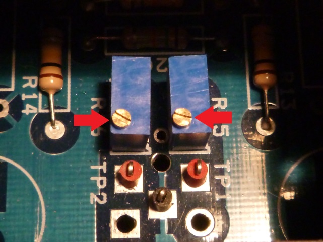
Note the variable resistors in the pictures below. These are adjusted while monitoring a voltage, to set the bias.
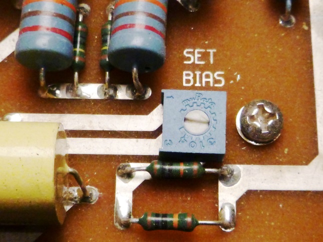
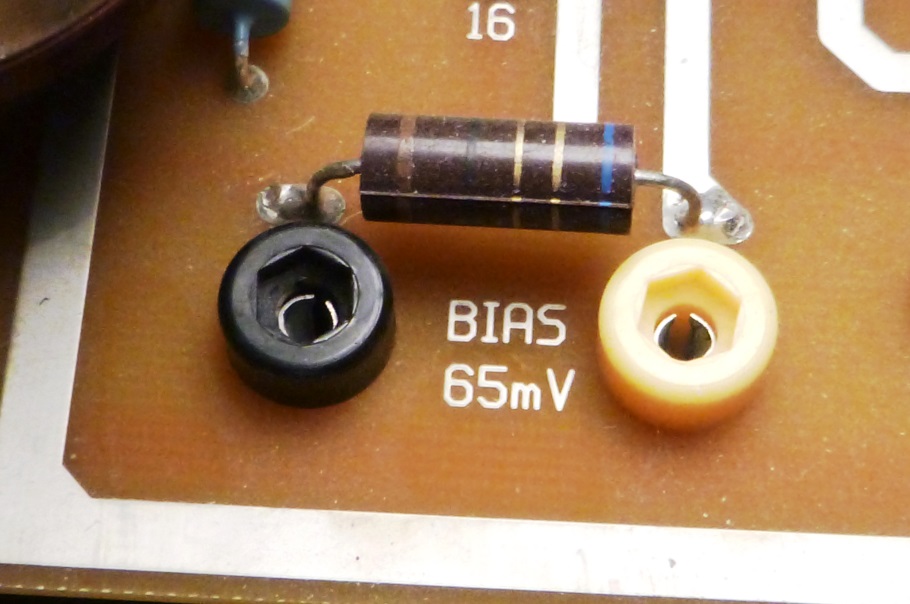
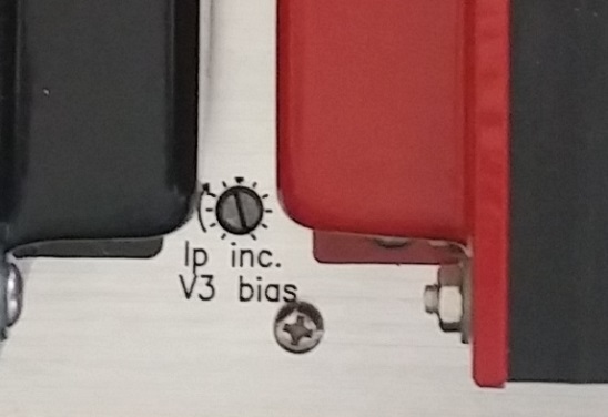
The circuit board in the picture below has the ideal voltage setting stated right next to the test points for meter probes. The owner’s manual is the other common source for the voltage set point. The voltages being measured are usually not more than 2 volts and are not dangerous. There are other voltages nearby in the 300 to 500 volt range that ARE dangerous.
If you are not sure, get an old tube hand to show you how to do it before attempting it yourself. Some amps, like the one shown below, don’t require removing a cover, so the adjustments can be performed without exposing the user to dangerous voltages.
Be sure to let the amp warm up for 10 to 15 minutes before setting the bias so that the components have a chance to stabilize. Music should NOT be playing when you make bias adjustments, but you may listen as the amp is warming up.
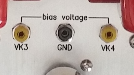
Set the meter to measure DC voltage, and insert or attach the meter probe to the test points as shown below.
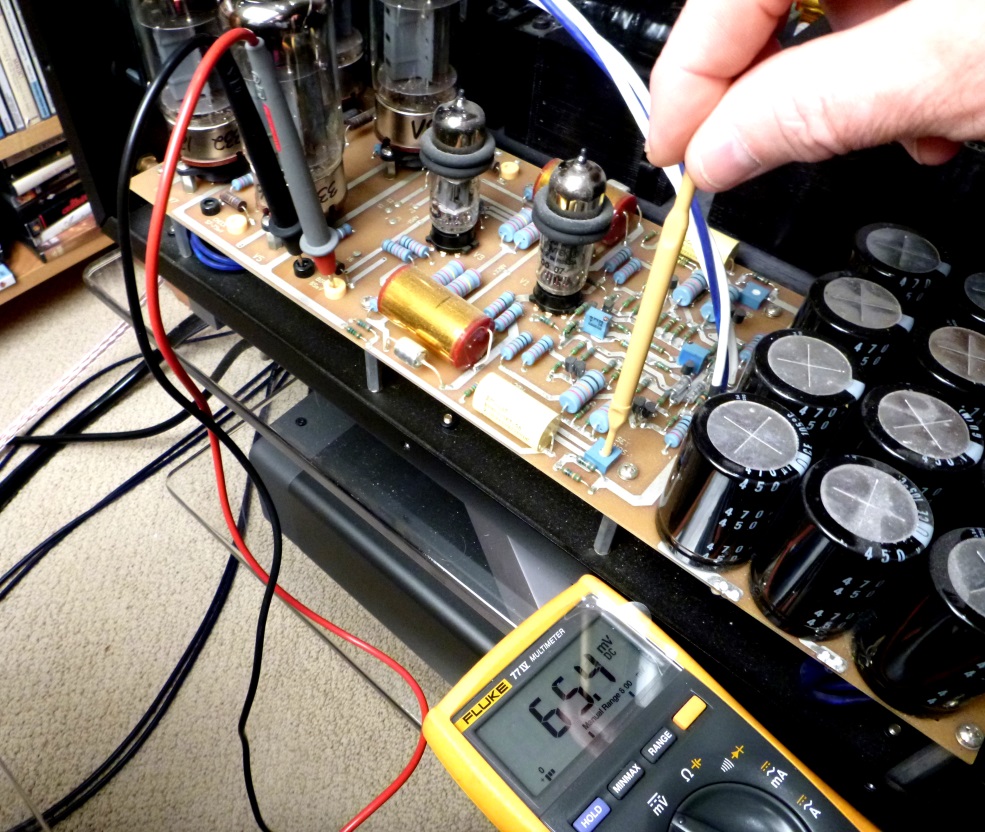
Carefully adjust the trimmer potentiometer for each tube to set the specified voltage as shown above. Repeat for the other tube(s) in the amp, and you’re done.
Please note that in the picture above, a special insulated adjuster is used. If one of these is not supplied with your amp it’s a good idea to get one, they are only a couple of bucks. If you drop a standard steel screw driver in to a live tube amp, you might get an introductory lesson in arc welding.
With a new amp, or when installing a new set of tubes in an amp, it’s a good idea to check the bias every week or so for the first month. Tube characteristics will likely drift a bit during break-in, and a quick adjustment of bias will nudge them back to the specified point. If you are replacing a worn out set of tubes, dial the bias back on the old set before you put the new ones in. This will allow you to start at a low bias setting and work up gradually. Starting with a bias that is too high can stress your tubes, and consequently stress you as well.
After that, check the bias every month or so, and adjust if necessary. The best time to re-check the bias is at the end of a listening session, before the amp is turned off. At some point, you won’t be able to adjust the bias to the specified setting. This is a signal that a tube is nearing the end of its useful life and should be replaced. If this is a stereo amp and the other power tube(s) were installed at the same time, chances are they will (all) need replacement soon.
A fixed bias push-pull amp has two advantages over a similar amp without bias adjustment. The first, mentioned earlier, is the opportunity to adjust the tubes for the best compromise between sound quality and longevity. The second is that distortion is minimised when both tubes (in the push-pull pair) are adjusted for identical current draw.
One of the cold hard facts of tube amps is that tubes can be a little flaky. If a new tube fails it will likely fail within the first 5 or 10 hours of use. It might cost a bit more, but buying tubes from a reputable vendor in matched sets can save money in the long run. A conscientious tube vendor will group and record a set of tubes characteristics. If, for instance, one of the tubes goes bad a month or so after purchase and installation, it’s relatively easy to get an identical replacement. See picture below for an example. Please note, I didn’t have a KT77 go bad. I’m just using this as an example of a vendor that puts in a little extra effort for the benefit of his customers.

Setting the bias voltage to the nominal value and setting all tubes identically is all you need to know to optimise the performance of your amp. I’ve avoided theory up to this point, but if you want to know the reasoning and math behind these adjustments, please continue. I’ll also cover power dissipation for those of you wishing to know about this subject as well.
Calculating Bias Current and Power Dissipation
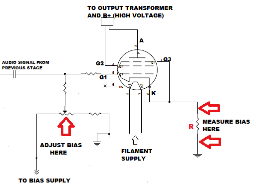
The schematic above shows the tube of a typical output stage. In this case it’s one half of a push-pull amplifier where another tube is essentially mirrored below this one, but for simplicity I haven’t shown it.
The tube is a pentode (5 elements, not including the filament). The 5 elements are the cathode (K), grids (G1, G2 & G3), and the anode (A). Old timers like me usually refer to the anode as the ‘plate’. I won’t get in to the theory of the electron flow within the tube, but if you are interested some links for further reading are provided at the end of this article. Though not shown, the anode and grid 2 are connected to the output transformer in what’s commonly referred to as an ‘ultralinear’ configuration. The output transformer is also connected to the high voltage supply usually referred to as the B+. In a typical hifi tube amp, the B+ is usually in the range of 350 to 500 volts!
The voltage you will be measuring across cathode resistor (R) is usually no more than 2 volts.
As you adjust the bias potentiometer (‘bias pot’ for short), shown on the left side in the schematic above, you are imposing a DC voltage on G1. This voltage controls the current flow through the tube. The current flow is manifested as a voltage across resistor R. The voltage across R will vary in relation to the current flow through the tube. A higher voltage across R equals more current flowing through the tube.
To determine the current flow through the tube we need to know two things, then do a little easy math. Once we know this, and find out one more piece of information, we can calculate the power dissipated by the tube.
We need to know the value of resistor R. This will be anywhere between about 0.1 and 30 ohms. The value can be found on the schematic for your amp, if one is provided. Internet forums are another source of schematic help, and if all else fails you could possibly read the resistor value from the colour code on the one in your amp, or measure it with a multimeter.
If you are not sure about what you are doing, seek advice. If you plan to nose around under your amps’ covers, the least you should do is unplug your amp and let it sit overnight. This will give the power supply capacitors time to discharge their potentially lethal voltages.
For the example schematic shown above, let’s say R is 5 ohms. And let’s say the voltage we are to aim for when we adjust the bias pot is 0.30 volts, measured across R.
To calculate the current flow through R (and through the tube as well), we use Ohms law:
E = I x R where E=voltage (in volts), I=current (in amps) and R=resistance (in ohms).
So: I = E / R or 0.30 ÷ 5 = 0.06 amps (or 60 milliamps).
This information on its own doesn’t mean too much, so we must continue if we are to calculate the power dissipated by the tube to see if it falls within safe limits or if we wish to, crank it up (or down) a bit.
Calculating Power Dissipation
We need one more piece of information to calculate the power dissipated by the tube. This is the voltage measured across points K and A on the tube in the schematic. If you are not comfortable measuring this voltage, it will be several hundred volts, don’t do it. Get someone who knows their way around a live tube amp to help. If that’s not possible, use the nominal B+ value from the schematic, that will get you close enough.
To calculate the power dissipated through the tube, use the following formula:
P = E x I where P=power (in watts), E=voltage (in volts) and I=current (in amps).
So: E (B+, either measured or from the schematic) x I (from the previous calculation).
For the example, assuming that the B+ is 350 volts then: 350 x 0.06 = 21 watts.
In the example above, the tube is an Electro-Harmonix EL34. The tube data is available on the New Sensor website.
Below is a copy of the pertinent information we’ll need. The values stated are the maximum permissible. Typical voltages, currents and powers (dissipation) in actual amps are significantly less.
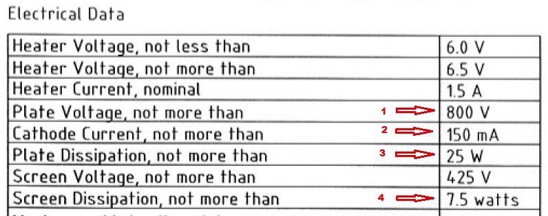
As far as our example goes, the plate voltage (1) 350 volts is fine because the max is 800. Cathode current (2) at 60 mA (milliamps) is fine as well. Screen (grid 2) voltage (shown between 3 and 4) is well above our B+ (350 volts) so we are within the allowed limits there too. For maximum power dissipation, we can add 3 and 4 together for a total of 32.5 watts.
This is where my analogy to setting the idle speed on a car engine breaks down a bit. The idle speed on an automotive engine is maybe 10% of the maximum revs. Nominal bias on output tubes is typically set to yield a power draw of approximately 70% of the maximum permissible.
70% of 32.5 watts is 22.75 watts so our example that dissipates 21 watts (65%) is a little low. If this was a real amplifier, cranking it up another 1.75 watts would not likely be a problem. To figure out the bias voltage setting for 22.75 watts dissipation, just work the two formulas backwards to arrive at 0.325 volts.
I’m sure the question forming in your mind is, “What if I run through the calculations and my amp is running the tubes at 55% dissipation, can I crank it up to 70%?” The answer in a perfect world would be yes, go right ahead. However, there are practicalities to be considered that might not make that possible. If we use the example above but assume that the amp manufacturer recommends 55% dissipation (17.9 watts per tube), we have a bias setting of 0.26 volts but more importantly the current flowing through each tube is 51 milliamps. Assuming a push-pull stereo amp with four tubes, that’s a current draw of 204 milliamps (51 x 4). If this is what the amp maker has recommended then cranking up the dissipation to 70% (65 milliamps per tube, 260 mA total) increases current draw by 27.5%. If the power transformer and/or the output transformers are marginally specified, a 27.5% increase might be too big an ask. I’m not saying amp manufacturers as a rule marginally specify their transformers, but some might. So my advice, in this case, would be don’t chance it unless you think a fireworks display in your listening room would be fun. As a rule of thumb I wouldn’t change the bias by more than 5% or so from the specified value without first receiving approval from the amp’s manufacturer.
Next Time
In the concluding part of this series I’ll discuss the other common type of bias (cathode bias) and talk about tube substitution considerations as well. If you have any questions, send them in now, and I’ll try to address them in part 2. I apologise in advance if I’m not able to answer specific amplifier questions or make recommendations. Unfortunately there are many more amps out there that I haven’t heard than ones that I have heard.
Read part 2 of the article here:
https://wallofsound.ca/audioreviews/amplification/output-tube-biasing-an-introduction-part-2/
Resources:
Enjoy The Music.com Vacuum Tube Tutorial http://www.enjoythemusic.com/diy/0713/vacuum_tubes.htm
Aiken Amplification index to white papers http://www.aikenamps.com/index.php/white-papers
DIY Audio Tube Forum http://www.diyaudio.com/forums/tubes-valves/
Most helpful, thank You.
Now what I need to do is decide what would be a good amplifier I don’t have one yet. Whether I go push pull or single ended are or what price range I should have not sure
David,
Thank you for your comment. I can only speak in general terms not knowing your room size, musical tastes, planned speaker choice, etc. Single ended amps are typically limited to 10 watts or less so are restricted to higher than average efficiency speakers, small rooms, limited loudness or a combination of these factors. Super-efficient horn speakers and single ended amplifiers often make good play mates. Small push-pull amps in the 15 to 20 watt range can work well with medium efficiency speakers if you don’t expect rock concert-like volume levels. My wife’s Spendor S5R speakers sound very nice driven by a modern interpretation of a classic Dynaco 15 WPC tube amp.
Hey buddy I just qw hoping u could help me out. Having an issue figuring out the Bell Carillon 6060 bias. Just wajt to know what it’s set at. I did the math and it has to be wrong. I’m newer to schematics. It uses all 4 on one. Single circuit cathode I guess u would call it. I can show u the schematic if you’ll get back to me. Thanks.
”Fixed Bias = Adjustable Bias”
No. ALL bias is ‘adjustable’, the question is HOW can it be adjusted. Fixed bias means more like ‘not cathode biased’.
Fixed bias is a confusing term, I think Steve explained it just fine in layman’s terms. Fixed means the user “fixes”, or adjusts, the bias. That clears up the confusion a newbie might have, thinking “fixed” meant “pre-set” or, locked at one setting. Autobias is a lot more obvious – the circuit compensates on its own.
This is not what it means. Fixed bias means that bias is provided by a separate negative supply, not by the cathode resistor, commonly known as self-bias. In self-biasing, bias will change with changes in plate current, therefore it is NOT fixed.
Now I explain what happened to me. It It the First Time that I real with tube amplifier and recently i purchased a used feZz audio titania amplifier.
At the beginning It worked perfectly, but After a wile It begun to distorce the output. So i Begun to set the bias of the four elettro Harmonix RT88 EH tubes according to the instruction of the amplifier manual –> 1 tube burned! because, for my inexperience, I do the setting without monitoring the voltage, because the probes of my multimeter were notizie perfect for this.
When the tube burned First I tuned completely right to left the potenziometer and then swhiced off the amplifier.
Previously i tried toset the otner 2 tubes ( of the left channel) but was impossible to set It properly.
Now i bougt an otner set of RT88 eh tubes and I’m waiting for them.
I bougt olso a new set of probes for my multimeter to monitor the V during the setting.
Now what Is the more sure way ti substitute the tubes?
Having turned completely on the right the potenziometer should damnage olso the new tubes?
Excuse my bad English and thanks for tour actention.
Hi Pietro,
When Steve is back he will likely have some comments for you. I have not heard of something like this occurring before.
Noam
Thanks a Lot….. some light in my despair!!!!!
Greetings Pietro,
Has your amplifier been modified so that the bias is adjustable by the user? The reason I ask is that when I read the specifications and the manual on the Fezz Audio website they only speak of automatic bias. Perhaps the automatic bias circuit is not performing correctly or if your amplifier has been modified something is wrong with the adjustment circuitry. Before you damage more tubes, I suggest you contact Fezz Audio for a recommended service facility close to where you live. I’m sorry I can’t be of more help but if tubes are burning out there must be something wrong inside the amp. If your amp has been modified a good technician should be able to show you how to set it up so you can check and adjust it yourself in the future.
Good luck and thank you for your interest in Wall of Sound.ca.
Regards, Steve Graham
Thanks a lot,
Mine is an old model before Fezz Audio introduced automatic adjustment of bias.
I’ll contact directly Fezz Audio and try to send them the amplifier for a revision.
Thanks again and have a Nice day,
Pietro
My Marshall TSL is set at 45mv each side, there is no plate voltage measurement etc that taken to determine how to set the bias, so why can’t I set the bias this way for other amps and set the mv to where it sounds good?
Darren, thank you for your inquiry.
Without seeing a schematic here’s what I think Marshall is doing: To save you the math and so you are not measuring very high (dangerous) voltages a low voltage across a resistor is measured. See the red “R” in the schematic above. Marshall has already done the calculations so that 45 mV at this point will also set the appropriate overall tube power dissipation. My ARC stereo power amp uses the same method.
When set to the 45 millivolts you mention the amp should be in its sweet spot (best compromise) for sound quality AND tube longevity. Adjusting the bias for a larger voltage across this resistor might make the amp sound a little bit better but you will be working the tubes harder and they won’t likely last as long. If adjusted too high past the tube’s limit their plates will start to glow red and their demise will be immanent.
I’ve heard of guitar players biasing their tubes lower for longer tube life but the sound is typically “colder” and unappealing.
Some amps have non-adjustable bias so you get what you get depending on the power tubes and how they age.
My advice would be to have a good amp tech demonstrate the measurements involved to calculate the actual power being dissipated by the output tubes and compare this to the tube’s specifications. The amp tech should also be able to make recommendations of how you can much you can deviate from the amplifier manufacturer’s value before cooking your amp or shortening tube life significantly.
Thank you for your interest in Wall of Sound.ca. I hope this is of some help.
Regards, Steve Graham
I have an integrated amp. Manufacturer’s recommendation is to set 0.3 to 0.35 volts bias or 30-35 mA.
If I set it 0.32v the amp reading shows around 24 mA which is lower than what is in manual. Should I go with volts or set the bias in amps. Tubes are EL34s. It is a class AB amp
Madan,
Thank you for your inquiry. You don’t say how you arrived at the 24mA figure. I’ll assume that if you set the bias so that 0.35 volts at the measurement point this will be equivalent to 35mA (0.035 amps) of current flowing through the tube. If we work the E=IxR formula backwards so R=E/I or 0.35/0.035 = 10. The resistor where you measure you the 0.35 volts is likely 10 ohms. If indeed it is 10 ohms then when you set the bias so the voltage across it 0.35 volts there must be 35mA of current flowing through the resistor and the tube.
If you suspect this is not the case, I suggest you take your amp to a technician familiar with tube amps. The tech should be able to suss out what’s going on and explain it to you in short order. It might cost you an hour of the tech’s time (perhaps $50 to $75) but it would likely be money well spent. I’m sorry I can’t be more specific concerning your measurement discrepancies.
Regards, Steve Graham
Muchas gracias por el articulo.
Greetings Héctor,
Thank you for your comment and interest in Wall of Sound.ca.
Regards, Steve Graham
Wow, an article on tube amp biasing open to musicians and hi-fi, and you actually get back to Q’s from folks….you’re a bigger man than me/I thought I had patience.
I sort of posed this question in 6L6 shootout by Tim Smith with a reader who has the same amp as me, waiting to hear. I have a Onix/Melody SP3 integrated amp, the manual says bias should be set to 1.15v. I assume this is for the stock 5881 power tubes, i’m using 7581A tubes and they sound great. I’m actually running them at 1.18v , which measures 35ma on my meter just to get a warmer sound as I did with the 5881’s. I don’t have a lot of spec’s on the SP3, does anyone know what the bias setting should be for the 7581A in this amp. Also, am I correct in my assumption that running the bias high or hot produces more body.
Thank Mike R
Michael,
I can’t comment on your amp specifically as I’m not familiar with it. But in general terms under-running the bias, in my experience (see my power tube shootout on this site), can lead to a somewhat cold and lackluster sound. A normal or slightly above normal bias can in some instances flesh-out the sound making it more ear-appealing.
The 5881 is essentially a 6L6G tube. 6L6G, GA and GB tubes all had about the same power dissipation specs. With the introduction of the 6L6GC (and it’s industrial equivalent the 7581) maximum dissipation increased by about 50%. It increased a bit more again with the 7581A.
All of this is a long-winded way of saying that increasing your bias setting from 1.15 volts to 1.18 volts (a 2.6% increase over nominal) should be no problem at all when using 7581A tubes.
One thing to monitor when increasing bias is the temperatures of your power transformer and output transformers. A 2.5% increase shouldn’t be a problem but don’t push your amp too hard.
Higher biases on output tubes can shorten their lives, but again, 2.5% more isn’t much especially if your musical enjoyment increases a lot.
Regards, Steve Graham
Thanks Steve, that all sounds encouraging. My transformers have plastic coverings, but when I put my hand on them there’s virtually no heat. The SP3 seems to be more popular than I thought so there may be readers out there with similar situations.
Again thank you, regards Mike R
I’ve had a couple of SP3’s, they’re great amps that you could buy for $400-500 (used) back in the day. I rarely see them up for sale now, and people want more for them. 👍🏻
Enjoy and thanks for reading WoS.
-Noam
Merry Christmas everyone, I’m having an issue with my Onix/Melody SP3 amp. When I check the bias settings, sporadically I’m getting a reading. Sometimes on the right channel, sometimes on the left, sometimes both and sometimes neither. Sometimes only one tube will read. My meter either reads the bias or reads 0’s. I’ve changed the battery several times and the meter reads house voltage correctly. I’m pretty sure it’s the amp, it still sounds great and reads the correct bias when it does read it. Anyone know what would cause this?
Thanks, Mike R
Michael,
Could it be that your meter probes are not making good contact with the amp measurement points? The fact that it reads correctly or not at all suggests a bit of housekeeping on the bias measurement connections might be in order. See: https://wallofsound.ca/audioreviews/accessories/treating-s-a-d-seasonal-amplifier-disorder/ The current drawn by the meter is very low especially at low voltages so a little bit of oxide or other grunge might be what’s giving you grief.
One of my home-brew Franken-amps (several designs stitched together into one amp) was giving me bias grief recently. The bias kept floating high or low on all four tubes. Once I corrected the bias supply (for the third time!) it mostly settled down. One tube was still floating +/- 30% from ideal. I replaced it with a new tube and its bias is rock solid. Pays to have an extra tube of even a pair handy.
Cheers, Steve
Hi Steve, bingo! You were right on the money. Seems the meter probes were the culprit, although I cleaned the bias sockets afterwards. Nothing seemed dirty to the naked eye, I used isopropyl alcohol 70% and it worked. If there’s a cleaner better suited for this situation please let me know. I really appreciate your help, thanks again. I’m sure this could help others with this problem, I should have thought of it myself.
Regards Mike R
Michael,
I’m happy it worked out. Try the link in my previous reply. The Deoxit mentioned in the article should do the trick for all connections. A small bottle (~$16) is available in the USA from Parts Express, Antique Electronics, or others. Tell your audio buddies about Wall of Sound.ca
Steve
Addendum: Hi Steve, cleaning the bias and probe contact worked, but only temporarily. So I ordered Caig DeoxIt because I wanted to do the whole system anyway. What solved the problem was to wrap the probes with aluminum foil, thereby increasing the contact area. I’ve been getting a consistent reading every time, just a little trick you and you readers might like to know about.
Thanks Mike R