
By Steve Graham
DIY EL84 Project: Part 2 – Circuit Board & Chassis Prep
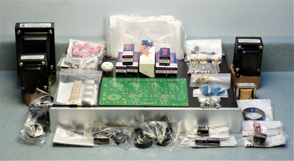
I strongly recommend that builders considering this project use the parts and chassis specified in the previous installment in this series. If builders go off-plan, positive outcomes are less certain.
This is not to say that if, for instance, different binding posts are desired or a different brand or type resistor is preferred, it should not be used. As long as these parts have the same rating or specification or are rated at a higher voltage or wattage, all should be fine. The capacitors specified in the parts list have been selected to fit the circuit board. If substituting other caps check their physical size and lead spacing.
As an example, the output binding posts I selected require ~1/4” mounting holes. Holes larger than about 3/8” are difficult to drill in 3mm thick panels. Most binding posts require 1/2” mounting holes. If you have the means to drill large holes, or have access to a tool and die shop, go for other binding posts if you wish. The large holes where the tubes protrude through the top plate are cut with hole saws. This can yield a fairly rough hole but the plastic grommets – an idea I stole from John Broskie – can cover this, as long as it’s not too rough.
I have endeavored to make sure the parts used are available from as few suppliers as possible, to minimize shipping costs. I’ve also used suppliers that usually have stock on hand. These are not necessarily the lowest cost suppliers but in my experience they all are reliable.
When it comes to chassis and layout, it may be unwise to substantially deviate from the plans presented here. A few bucks might be saved using a smaller chassis, but the downside might be an amp that hums unacceptably. Employing the parts, chassis and layout used for this project, as well as the wiring procedures I detail, should make success a near slam dunk.
To work:
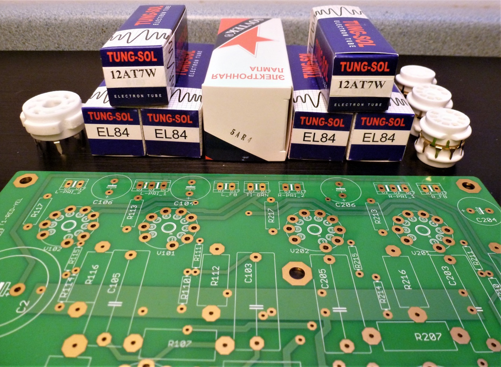
Metalworking is a bit of drudgery, well more than a bit actually. But it’s a necessary evil we must live with and put behind us before assembling the circuit board and wiring up the transformers. As mentioned previously, don’t assemble anything on the circuit board yet. It needs to be free of components to aid in chassis layout.
Perform the attachment tasks in the order given below.
Attachment 1: Circuit Board Prep
Attachment 2: Chassis Pre-assembly
Attachment 3 (Revised): Top Panel Layout
Attachment 4 (Revised): Drilling the Top Panel
Attachment 5: Bottom Front and Rear Panel Layout and Drilling
Next time in Part 3 we assemble components onto the circuit board. Part 3 is ready and will be posted midweek.